OIL WATER SEPARATOR DESIGN (OWS) TO REMOVE OIL
INNOVATIVE OIL WATER SEPARATOR DESIGNED TO REMOVE
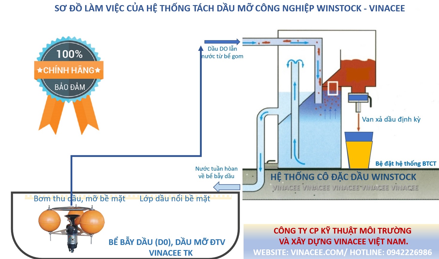
Oil Water Separators are designed to precipitate and remove suspended solids and essentially all free and dispersed, non-emulsified oil, from an oil water mixture on a once through basis. The design utilizes the difference in specific gravity between suspended solids, oil and water (buoyancy force) enhanced by the use of projected plate surface area and coalescing plates.
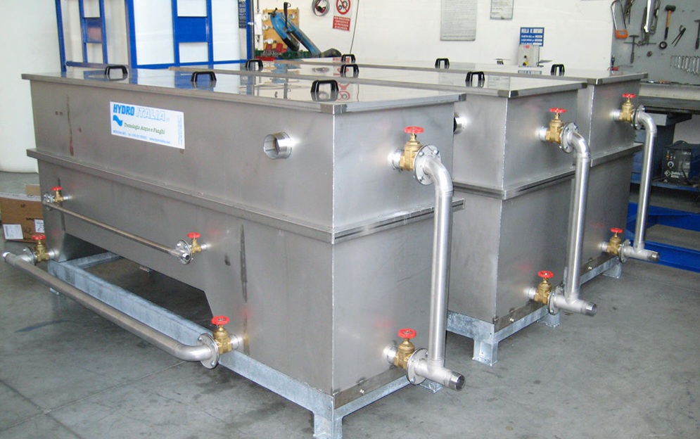
The clarifier/separator is a special purpose prefabricated system comprised of a tank containing an inlet compartment, sludge chamber, a separation compartment, and clean water outlet chamber.
Tank: The tank can be constructed of stainless steel, carbon steel, fiberglass or plastic and equipped with vapor tight covers for vapor control, gas vents and access openings.
Inlet Compartment: The inlet compartment has to have sufficient volume to effectively reduce influent suspended solids, dissipate energy and begin separation. The inclined plates will sit elevated on top of a sludge chamber. As the water moves upwards the suspended particles have their upwards velocity interrupted by the inclined plates. These particles drop down and slide down the inclined plate and join larger previously settled particles in sludge hopper.
Sludge Chamber: Located before the separation/coalescing compartment, the sludge chamber serves to settle and prevent any solids from entering the separation chamber or the clean water chamber.

Separation/Coalescing Chamber: The oil separation chamber contains coalescing media. The media’s plates are placed at 90 degrees to the horizontal or longitudinal axis of the separator. Spacing between these elements is optimized for the removal of a minimum of 99.9% of free droplets. The elements are positioned to create an angle of repose of 90 degrees to facilitate the removal of solids that may tend to build up on the coalescing surfaces, which would increase velocities to the point of discharging an unacceptable effluent.

Laminar flow at a maximum designed flow rate shall be maintained throughout the separator including entrance and exit so as to prevent re-entrainment of oils with water. Flow through the coalescing media shall be crossflow perpendicular to the vertical media elements such that all of the coalescing media is available for use.
Baffles: An oil retention & underflow weir, and overflow weir prevent re-suspension of settled solids.

Oil Skimmers: Oil skimmers are usually installed in the clarifer compartment and the oil separation compartment to decant the separated oil to a oil storage tank.
Polishing Packs: Oil Absorbent bags are often placed in front of the clean water chamber to absorb any remaining small oil droplets and polish the water.
Clean Water Chamber: The final stage of an oil water separator is a clean water chamber which allows the water to leave the separator through the clean water outlet port.
Auxiliary Systems: Pumps and controllers can be provided for water transfer and semi-automatic operation. Ozone systems are often used for odor control.

Viết bình luận
Bạn đã gửi bình luận thành công. Xin cảm ơn!